
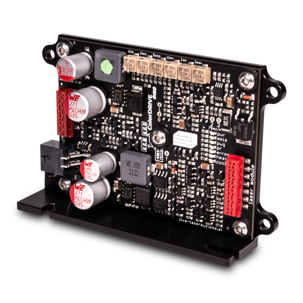
ColorDRIVE Control Box PCB
Control PCB for the ColorDRIVE one driver. Fits perfectly on the back of the driver.
Can be used to manually set modulation voltage via potentiometer or external signal (BNC or cage clamp).
Displays state of interlock, power reduction and ColorDRIVE sensor error.
Features a screw cage clamp connector or for external interlock and modulation signal (interlock modes include: line break, line make and "to ground"-mode).
If you want us to mount the Control PCB to your ordered ColorDRIVE one, we offer this service optionally. Please select the respective option when ordering.
Comes with:
- short flat ribbon cable
- ferrules
- interlock bridging cable
- mounting screws, washers and hex-nuts
Specification
| Connector in | 1x 6/4pin Screw Cage Clamp Connector 1x BNC connector (optional) |
| Connection out | 12pin, ColorBUS connector |
| Control options | Potentiometer for modulation, switch to choose between on-board modulation and external signal |
| Mounting | 4x M3 screws |
| Dimensions | 102mm x 61mm |
Downloads
Technical Drawing tbd.
Manual tbd.
Article in Shop

Diode/TEC Drivers
Control PCB for easy manual control of any ColorDRIVE one with option for external signal input.
(MwSt. excl.)
Price without discount40,00 €
Compatible Accessories
Diode/TEC Drivers
High performance diode driver with or without integrated TEC driver.
(MwSt. excl.)
Price without discount55,50 €